Arrow Fat Left Icon Arrow Fat Right Icon Arrow Right Icon Cart Icon Close Circle Icon Expand Arrows Icon Facebook Icon Instagram Icon Hamburger Icon Information Icon Down Arrow Icon Mail Icon Mini Cart Icon Person Icon Ruler Icon Search Icon Shirt Icon Triangle Icon Bag Icon Play Video

News

Clutch Hydraulic TECH - Concentric slave and clutch master setup

AIR GAP, FREE PLAY, AND CLUTCH MASTER CYLINDER SIZING

Want to know the easiest way to burn up your clutch and/or release bearing?

LACK OF AIR GAP!


WHAT IS AIR GAP?
When it comes to clutch setups with a concentric slave cylinder, air gap is space for the clutch room to grow as it wears. Your clutch discs get thinner and thinner as they wear, when this happens the diaphragm fingers get "taller" and move towards the bearing more and more. The air gap you setup allows the bearing to move backwards and away from the clutch to allow for this growth/wear over time.

There is no set time or mileage on how long this takes to lose all your air gap, but it depends on the clutch friction material, your driving style, and overall abuse and amount of slip the clutch sees. Riding the clutch from a stop will reduce the clutches life and reduce the air gap at a faster rate.

Manufactures differ on their recommended air gap distance, with Tilton's recommendation being 0.125" which is about 3mm. I like to set my gap between 3 and 4mm, usually closer to the 4mm as it buys a bit more wear time before needing adjustment.

WHAT HAPPENS WHEN THERE IS NO AIR GAP?
The clutch loses its clamping force, because now the diaphragm cannot fully release and clamp the discs as tight as designed. This can make the clutch slip and will burn up the clutch very quickly if not addressed. It will also burn up the release bearing. The bearing is only designed to see pressure when the clutch pedal is pressed down, not a constant load like it would see when the diaphragm applies force to it.

WHAT HAPPENS IF TOO MUCH AIR GAP?
The more air gap you introduce, the less amount of sleeve is left available to stroke the clutch. This can cause an overextension of the bearing, and can cause failure. Usually complete loss of pedal, and most of the time it tears the seal and causes the bearing to need to be rebuilt.
 
INITIAL AIR GAP SETUP
When you take your initial air gap measurement, the gap is the distance between the bearing and the clutch fingers. BUT, after you BLEED the clutch, now the bearing will be in contact with the clutch fingers. The bearing will not apply heavy pressure to the fingers but it will constantly ride on the fingers. So, after bleeding your AIR GAP now lives in the sleeve of the bearing. After you bleed your clutch, double check by looking in your bellhousing at your bearing to make sure you see the 3-4mm of air gap in the bearing sleeve. Below are pictures illustrating how the gap should look.

FLAT FACE AIR GAP:
AIR GAP TILTON FLAT FACE BEARING
RADIUS FACE AIR GAP:
 
TILTON BEARING SPECIFICS
The Tilton 6000 series have two sleeves. On the flat face bearing the back of the bearing will sit flush with the top of the housing. The radius bearing has a stepped lip sleeve. The gap will look a little different on radius bearings as it will be that 6mm long stepped section + 3-4mm of air gap. I attached pics here so you can see it just like it should look when you look inside the bell from the side of the bearing.

LOOKING IN AT FLAT BEARING THROUGH BELLHOUSING:
AIR GAP TILTON 6000 BEARING GRANNAS TWIN DISC
 
Flat bearings are used on almost all the twin discs I sell, any pressure plate with the rounded tips/flare at the inner ring of the diaphragm fingers. The radius bearings are used on the single discs and the smaller ST215 twin discs, as well as OS Giken clutches and other "straight finger" clutches.
I've talk about this in the older youtube video but sometimes I feel like its not something people grasp well without pictures.

AIR GAP SETUP VIDEO:

CAUTION: OVEREXTENDING
Your release bearing has a travel limit. Take caution when setting it up! If you have 1" of total travel, and your air gap is set to 0.25" that means you only have 0.75" of travel distance left before the bearing overextends. When this happens you usually lose all your clutch pressure, it tears the seal, and you will be pulling down your transmission to fix this. Always make sure you do not have too much air gap.

Your clutch pedal stroke and master size also plays a big part in the amount the bearing will move. So, if you have a large bore master, and a lot of stroke in your clutch pedal, you may need to use a pedal stop, or what I do, is adjust the clutch pedal using the master rod downward towards the floor, and use the actual floor in the car as the pedal stop. The way I set these up, is about 1/2" of movement off the floor before the clutch starts to grab. This way, you have wiggle room but not too much to where you overstroke the diaphragm or overextend the bearing.

MASTER SIZE
Your master size should be determined based on the amount of distance (stroke) the clutch diaphragm requires for full release, along with the relation between your master bore size and the clutch pedals stroke amount. For example, if your clutch requires .440" of travel, then you would want to get a master that is just above that in total stroke amount. 
 
Here is a chart showing Tiltons release bearing + Tilton master when getting a full 1.1" of stroke from the clutch pedal.

Bore Diameter

Max HRB Stroke

Fractional (in)

(in)

5/8"

0.265

7/10"

0.333

3/4"

0.382

13/16"

0.448

7/8"

0.520

15/16"

0.596

1"

0.679

1-1/8"

0.859

 
The good thing is, I have done all this work for you, and when i sell a clutch, I set it up with the proper master sizing to make it work properly. When you buy a clutch from anywhere else, like Summit Racing, TURN14, etc... do they do that R&D for you? Hell no! But, that is why you buy from me instead of those guys right? From an actual guy who makes stuff, a person with hands-on experience, not just a website selling you a product and making money on it. I am not trying to be cocky, but you will see a lot of other vendors selling products and using my recommendations, riding my coat tails on this work that I have done.

CLUTCH MASTER - FREE PLAY
Since we are talking hydraulic system, lets also talk about the master. In your master cylinder there is a bypass valve, this valve releases the pressure from the master, if the piston in the master does not return back past this bypass port, the master will continue to build pressure like a pump. This will cause HAVOC, and can destroy a clutch, destroy your bearing, etc. Basically what will happen is your release bearing will push in more and more and more on the clutch diaphragm, reducing its clampign power, and will burn up the clutch, burn up the bearing. Catastrophic stuff... MAKE SURE you have free play at the top of your clutch pedal where the clevis attaches. If you pull the pin out of the clevis and the clevis shoots backwards towards the seat, you do not have free play. Watch this video for more info on that.

CLUTCH MASTER TECH VIDEO:

Continue reading

NEW ULTIMATE 8.8 rear covers and ULTIMATE 8.8 KITS are now available

The new 8.8 kits are now available for the MKIV Supra, Lexus SC, Lexus GS, and Lexus IS300 platform.

MKIV Supra / Lexus SC / Lexus GS complete kit

IS300 complete kit

These kits eliminate the two step install process, have a deeper cover for more fluid capacity and less "splash" which was why a catch can was needed on the old setup. This new setup does not require a catch can. They also feature a side fill port, so servicing these kits is now much easier with the diff installed in the car.

The video above is a quick overview of how to install the cover on your 8.8 case.

I am also selling the covers by themselves, so if you have a GEN1 kit with the rear girdle, you can upgrade to this new cover. This cover is also available as a fabrication kit, so if you want to swap a Ford 8.8" into a chassis where i dont make a kit, the new rear plate fab kit setup will give you a head start on getting it mounted. Link below will direct you to the cover by itself.

Ultimate 8.8 rear cover

ANOTHER THING: I can build diffs again... in limited quantities... So if you want a full kit WITH a complete pumpkin, built and ready to go I got you covered. The Tbird cores are really hard to find, but they can usually be found 1 by 1 at a local junkyard. So if you source one, and can send the core to me, we can build it for you.

BRZ/FRS/86 Customers:
The kit may fit into a BRZ also, but i believe the left hand side of the subframe may need a bit more trimming than desirable. the old kit required some trimming but this rear mount is a bit taller. I am willing to work with a BRZ customer to get it test fitted if you are looking.


Continue reading

Race recap - Bradenton FL "The Reunion" - Compound Turbo exploded, 6.59 timing erro

We had a compound turbo failure at the Reunion race, as well as running 6.59 (on a timing system error, DOH!) so that pass didn't count. but we have the short track on the car worked out now, with some really consistent, quick 60 foot times. I think we will see a 1.0x sixty foot time soon.

We had a consistent race car, multiple 7.0 passes, then a 6.90 and it was on another 6.8x or so pass until 2nd gear in round two when the "small" compounded turbo let go. We will be making some changes and coming back out stronger and faster than ever.


VIDEO BELOW

Continue reading

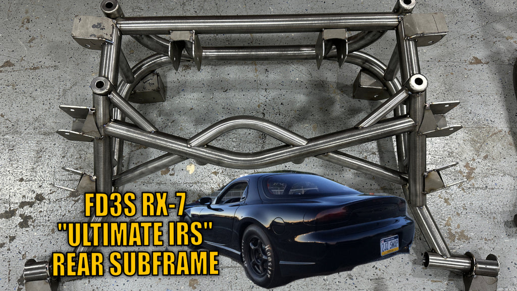
Announcing our new FD3S Ultimate IRS tubular rear subframe

Our first prototype subframe is complete and ready to show it to the world. 

This is a complete bolt-in rear tubular subframe for the 1993-1995 Mazda RX-7 (FD3S) chassis. This is 100% chromoly, so it is not only lightweight but extremely strong. The bare stock stamped steel subframe is around 30 lbs, this bare subframe is 10 lbs heavier, weighing it at only 40 lbs. This small 10lb weight gain is a small price to pay for the increase in chassis stability and strength. The stock subframes have been known to tear, especially when upgrading to an 8.8 rear end and welding in bars.

The subframe is available bare, powdercoated satin black, or powdercoated a custom color of your choice.

This will make the entire IRS suspension more rigid. Removing the play and twist from IRS suspension systems is key in making it work better. It weighs only 10 lbs more than the stock subframe and adds a ton of strength and rigidity to the chassis. It's like adding a roll cage to the rear of the car.

The subframe cradle uses all the factory mounting locations to the chassis and  stock locations for all suspension arms. This is also designed to work with the factory spindle. You can use all factory control arms other than the lower control arm (that has the eccentric bolt) - this subframe does not use the eccentric bolts, so you will need to have an adjustable arm there to adjust camber.

For the differential, it also uses the stock mounting locations, so you can use stock differential or an aftermarket rear end kit like my 8.8" or 9" kit. For example, you can see my FD3S 9" kit in the pictures.

For guys who already have an 8.8 rear end, this subframe will work with existing Ronin 8.8 customers as well, so if you already have the Ronin kit, you can direct swap out this subframe for your stock modified one. You can then sell your modded 8.8 subframe and recoup some of the costs.

This is something I have wanted to build for quite some time, so seeing John bring this to life is really awesome to see.

I am going to offer *** 12 PRE-ORDER SPOTS *** and they are available now.

It will be available to work with the stock rear, ford 8.8" rear, and ford 9" rear. More details are on the product page here --> FD3S Ultimate IRS Rear Subframe

Here is a video i made showing the subframe in the car and also a little overview of my FD3S collection as well.


Continue reading

186mm compound turbo 2JZ supra dyno

DYNO VIDEO IS UP!

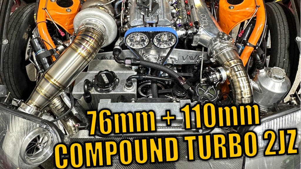
We were able to get a good baseline of the new bigger compound setup. We are now running a NextGen 7685 as the "small" turbo and a GEN2 110mm promod as the "BIG BOI" turbo. Results are in the video below!

The wild thing is, we are running 186mm worth of turbo on a 193 cubic inch engine. We have lots of turbo, plenty to make big power!

Please subscribe to our youtube channel for this continuing series!

Continue reading

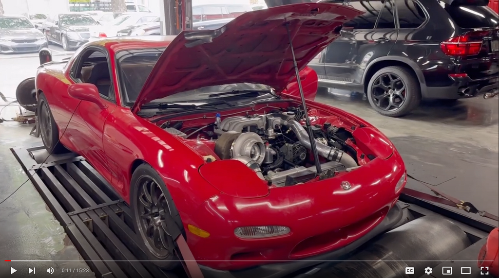
Grannas Supra COMPOUND Turbo System Dyno Day

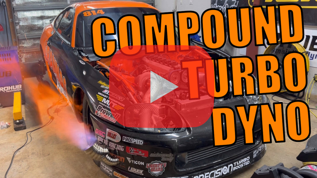
We got the car on the dyno to get a baseline and start to dial in the setup so we can go to the track and start testing. We ran out of time today, but got it to where we are more comfortable on higher boost levels. We stopped at 48psi for today we will turn it up all the way at the track.

Check out near the end of the video where i show the difference between the old turbo spoolup and the new compound setup. Major, major increases on low rpm horsepower. This will help combat small displacement/big turbo problems and help us get out of the hole way better!

I know this may not be the HUGE dyno numbers everyone wanted to see, but again we are only at 48psi and we normally run 80. i am saving the big power tuneup for the track.


Continue reading

COMPOUND TURBO SETUP 2JZ SUPRA

ORANGE MAN BAD'S NEW COMPOUND TURBO SETUP!

compound turbo 2JZ

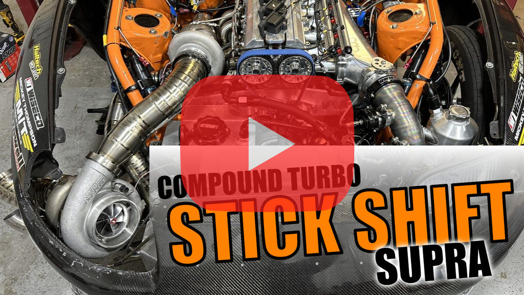
Check out this video of our new compound turbo setup build - in the video you will hear it fire up, and i will explain how the setup works and why we did what we did here.

Hoping for new personal bests and hopefully a new Stick Shift / H-Pattern world record

VIDEO BELOW

Continue reading
Grannas Racing Rotary to TREMEC T56 Magnum swap makes things simple

I had issues breaking factory mazda transmissions when making 650+whp... So I did what I always do... and created a kit to make a T56 Magnum fit in the car. SEE VIDEO AT BOTTOM OF PAGE

Grannas Racing 13B 20B RX-7 FD3S transmission kit t56 magnum tremec

My GR700A kit for rotary engine applications makes adapting a T56 Magnum to a rotary a breeze. The bell will work on manual or auto rear plates, same thing as swapping a factory auto car to a factory manual, but in this case you'll be putting in a much stronger transmission.

The first rotary kit I am releasing is the most common asked for application, the Rotary FD3S RX-7 GR700A kit. This kit uses a Tremec Magnum XL, along with my offset shifter to allow for a perfect dead center placement in the OEM transmission tunnel. This kit fits without any modification to the tunnel itself, no hammering, no cutting.

Grannas Racing Rotary RX-7 FD3S mazda transmission dyno tune 13b 20b 12A

The GR700A kit uses our proprietary cast aluminum bellhousing, which is a direct fit, no need for adapters or any other nonsense. If you are buying a complete transmission kit, it will arrive with the crossmember, mount, starter, shifter, and all hardware required. We also will machine the T56 magnum front plate and center case to allow the starter to clear the transmission. This is the Grannas Racing difference... I am very meticulous about making sure everything fits as best it can, and that you get everything you need to make this a painless install.

Grannas Racing FD3S shifter position RX-7 RX7 t56 magnum 13b 20b rotary

I recommend the Tilton ST215 clutch with these setups, which drives super smooth, and has two different power capacities. The sprung-hub organic twin disc is good for 600-650 torque at the wheels. And the cerametallic rigid twin disc is good for 850-900 torque at the wheels. You can see in the video below just how amazing this clutch drives. It is quiet and has a wide engagement range to make for a stock-like clutch experience while having the ability to hold big power.

Here is a video showing my personal car which was used for the R&D of this kit. No more third gear issues! Smooth as silk operation even at high RPM shifting.

UPDATE --- NEW VIDEO HERE!

Continue reading

What Pilot Bearing to use with LS and T56 Magnum

There are 3 Chevrolet LS pilot bearings with different OUTSIDE dimensions. This guide will help determine the size for your engine. 

LS1 LS6 LS3 LS2 Pilot bearing inner crank t56 magnum magnum-f

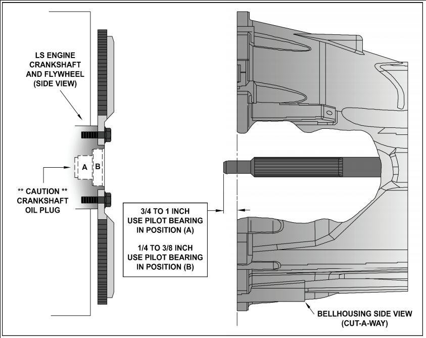
When using the TREMEC aluminum bellhousing or the Quicktime Chevy LS1-LS2-LS3-LS6 bell (RM-8020) with the 5.555" height, you will be using the "inner" pilot which is marked as "A" in the diagram above.

Pilot bearing “A” is the smallest outside diameter 1.094" outer diameter bearing that fits into the innermost pocket of the crankshaft flange. This bearing is typically with T56 and T56 magnum transmission combinations. NOTE: if using the small GM pilot bearing, the internal O-ring seal faces the transmission when installed properly. You can get it at local Autozone or Napa - Dorman part# 690-057 or ACDelco/GM 14061685

If using the Quicktime Small Block / Big Block bell housing (RM-6023) with the 5.950" height you will use the Pilot bearing "B".

Pilot bearing "B" is a 1.705" outer diameter bearing that fits into the outer pocket of the crankshaft flange. This bearing is used with Transmission/Bell housing combination from a 2003 to 2012 GM vehicle. NOTE: This is a double sealed bearing and it may be installed either direction into the crankshaft. You can find this local at NAPA / Autozone part #12557583

IMPORTANT NOTE: many GM LS engines use a press-in oil seal plug deep inside the crankshaft flange. DO NOT move or disturb this plug when removing or installing a pilot bearing. Your old pilot bearing must be removed by means of a mechanical pilot bearing puller. DO NOT attempt to use a “hydraulic” (grease or bread) method to push-out or remove your old pilot bearing! 

The best method to determine the correct pilot bearing position for your application is by using a straight edge or yard stick across the front of your transmission Bell housing and measure the distance that your transmission input shaft protrudes past the front of the bell housing. 

If your transmission input shaft dimension is between 3/4 to 1 inch (19mm to 25.4mm) use the SMALL diameter pilot bearing in crankshaft position "A".

If your transmission input shaft dimension is between 1/4 to 3/8 inch (6.3mm to 9.5mm) test fit the MEDIUM outside diameter pilot bearing into crankshaft position "B". The pilot bearing should be a slight press fit into the crankshaft. If the MEDIUM diameter bearing is a loose fit, please use the LARGE outside diameter bearing for a slight press fit into the crankshaft.

Be sure to install your pilot bearing into the crankshaft by driving or pressing on the outermost part of the bearing ONLY. The pilot bearing must be straight and fully seated into the crankshaft. DO NOT FORCE the installation. Once installed, the inner portion of the bearing must spin freely and smoothly. 

Continue reading

Should I index my bellhousing?

Do you need to index your bell?
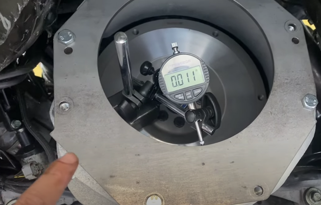
I do recommend checking runout on all bellhousings with an index plate. Yes, including the cast aluminum bell I sell. Any performance transmission setup should be within .005 runout of centerline. When I first setup these cast JZ bells I was really confident we would not have to do any indexing, we had 10 blocks we used for getting data... but after sending out 400+ of these bells we have found more inconsistencies in the blocks. We started noticing more and more customer's toyota blocks who are more out of spec than others. 

Machining Tolerances
We are within .002 on the bells, and consistent, so the inconsistency comes from the blocks... For example, i can take a few of my bells on the same block back to block and get pretty consistent numbers. But if you take one of my bells and try it on 10 different blocks the consistency does not follow. this tells me its a cast block machining tolerance issue.

What are your odds of being out of index?
While it is a smaller percentage (about 15 in 400 bells sold) that have shown an out of index condition, so I think it is better to play it safe and just check these to be sure. Out of index can cause premature failure of the input bearing as well as uneven wear and heat in the input gear. A tell-tale sign of an out of index bell can be a lot of rollover noise coming from the transmission. This is due to a side-loading condition on the input which over time can cause transmission issues. I do index plate rentals for any customer who purchased a bell or kit from me. 

TECH TIP:
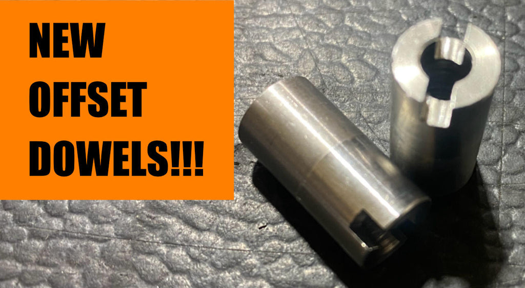
To remove your stock dowels, i recommend soaking them in a penetrating oil and let them sit overnight. Use a pair of heavy duty vice grips and slowly work them back and forth. If the get tight, heat applied to the block around the dowel may be needed

Here is a quick video I did on indexing and offset dowel install:

Continue reading
  • Page 1 of 10
  • Page 1 of 10